Shredder
APPLICATION
Equipment designed for primary – secondary shredding of different types of resistant materials such like plastics, pruning, wood chips, animal biomass, textiles, aluminium, bronze, brass, and ferrous alloys of low mechanical resistance.
FUNCTIONING AND PROCESSING
The shredding process starts with the introduction of the material to be treated into the hopper of the equipment. The hooper is equipped with a press moved by hydraulic cylinders, pressing the material towards the rotor of the shredder , in this way it is possible to shred whatever elements independent its geometry (bars, laminated rolls, planks, pallets ,boxes, etc…).

The press is continuously pressing the material against the cutting rotor. When the motor consumption of the rotor is too high or too low (no material to be shredded), the press returns to the rear part of the hopper and preventing the entry of new material or preventing the rotor from a possible shearing with excessive torque. This movement will be controlled alternatively by a PID regulator and an adjustable timer.
The reduction rate (output dimension of the material) is guaranteed by a constant distance between the mobile cutting knives and the stationary cutting knives. Once cut, the material rotates with the rotor and moving along the semi-circular screen which is situated at the bottom side of the rotor. When the material particles have reached their desired dimensions in the first shredding cycle, these fall through the holes of the screen, but if bigger than the desired dimensions, they will return to the shredding chamber, which process will be repeated until the material particles have reached their desired dimensions (the average time of a cycle is 0.5s therefore the shredding process will only take a few seconds).
Finally the shredded and calibrated material falls into a screw base extractor where it will be conveyed to the next stage in the system.
SHREDDING PROCESS

The material to be shredded is pressed against the rotor of the shredder

The rotor cuts by shearing the material using the blade of the knife

The semi-circular screen around the rotor calibrates the output dimensions of the particles

The output particles present a very homogeneous dimension which facilitates its processing afterwards
CONSTRUCTION

B: Rotor of shredder
C: Drive
D: Transmission
E: Multiplicator by gears
F: Knife holder + cutting knives
G: Adjustable stationary knives
H: Extraction screw for treated material
CUTTING PROCESS
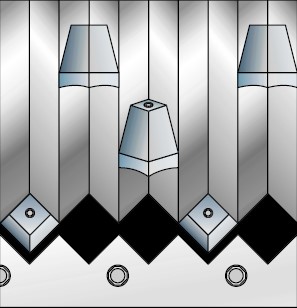
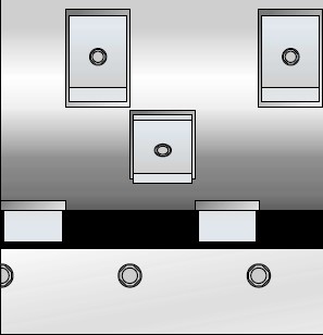
There is a wide variety of cutting processes for every kind of materials to be shredded, the most important parameters are the dimensions of the cutting blades, the shape of the cutting blades, the cutting angle of the cutting blades, cutting speed, etc…these parameters result in big differences which have led to the following cutting systems:

Integrated triangle

Cylindrical triangle

Cylindrical rounded

Cylindrical rectangular
CHANGE OF THE KNIVES
An important aspect in all actual applications is the energetic efficiency, therefore the energy consumption of all equipment. The efficiency in the shredding process is created by a minimal torque of the main rotor, consequently we have to minimize the tangential forces of the cutting taking into consideration the following factors:
- The cutting geometry should be adequate for the material to be shredded.
- The cutting speed should be precise according to the production hours.
- The cutting blades should be made of the proper material and should have the proper thermic surface treatment.
- The cutting blades should be in good conditions.
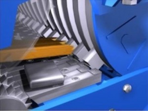
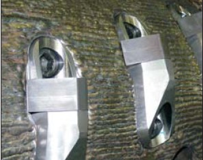
For maintaining the cutting blades in good condition, an adequate maintenance is required which should be as simple as possible. For all SECON/DSG shredders, this aspect has been perfectly studied and analysed. The solution is to make the cutting blades independent from the rotor so that they can be mounted in a reusable blade support in a way that these cutting blades can be used four times guaranteeing a very long lifetime. The automatic inspection door can be opened in a few seconds and allows an easy access towards the shredder chamber facilitating the maintenance process enormously.
TECHNICAL SPECIFICATIONS
| Dimensions input (width x length) | 3050×1500 mm |
| External diameter including knives (1) | 800 mm |
| Speed rotor rotation | 250 rpm |
| Nº of knifes | 80/160 |
| Geometry of knives | Triangular/Redonda/cuadrada |
| Quality of knives | Hardox-500/600/650 |
| Average superficial hardness of knives | 500/600/650 HB |
| Max. punctual hardness of blades | 600/700/800 HB |
| Distribution of the knives on the rotor | Lineal /spiral/lineal-espira |
| Diameter axle at max. flexo traction | 300 |
| Thickness rotor | 80 mm |
| Quality rotor | UNE-F-1140 |
| Nº of stationary knives | 12 uts in 6 jaws |
| Geometry knives | Triangular/Redonda/cuadrada |
| Quality knives | Hardox-500/600/650 |
| Capacity of drive mechanism | 160 Kw x 2 uts = 320 Kw |
| Nº of installed motors | 2 uts |
| Max. capacity admissible for shredder | 440 Kw (2m x 220 Kw) |
| Type of transmission | Poleas dentadas / Direct-drive |
| FORCES WITH MAX. CAPACITY INSTALLED | |
|---|---|
| Max. torque of cutting | 300 Kn |
| Average nominal force of cutting | 2.000 N |
| Average max. force of cutting | 5.600 N |
| Max. puntual force of cutting | 167.500 N |
| FORCES WITH INSTALLED CAPACITY | |
| Max. torque of cutting | 14.5 Kn |
| Average nominal force of cutting | 580 N |
| Average max. force of cutting | 1.620 N |
| Max. puntual force of cutting | 48.575 N |
| Press drive | By hydraulic group |
| Opening/closure drive of shredder chamber | By hydraulic group |
| Capacity hydraulic group | 9 Kw |
| Opening/closure time hydraulic press | 30 s |
| Max. pressing force | 300.000 N |
| Passing screen | 10/20/30/40/50/60/70/80/90/100 mm |
| Thickness screen | 10/15/20/30 mm |
| Geometry screen holes | Cuadrado/redondo/rectangular/coliso |
| Quality screen | HARDOX-400/500/600/650 |
| Hardness screen | 400/500/600/650 HB |
| Production according to hardness and dimension of material to be processed | 125-140m3/h (1) |
| Mass | 33.450 Kg |
1) Depending on the material to be shredded, according to the dimensions of input and desired output, the type of knife and the dimensions and shape of the screen might change, and with all this, the output flow.
ADVANTAGES
- To avoid premature failures/breakage, bearings and gear boxes are SEPARATED from the hopper of the shredder and isolated by a concept of “double labyrinth”.
- Gear boxes with direct-drive maintenance free, with carburized, hardened and ground gears, calculated for a lifetime of over 100.000 working hours.
- Input hopper designed in order to let all fines particles enter the hopper of the shredder.
- Extremely rigid structure built in forged steel, electro-welded, with a high elastic limit to support overloads.
- Double row roller bearings dimensioned for a lifetime of over 100.000 working hours.
- Mobile and static cutting knives constructed and manufactured of anti-wear steel and easily exchangeable, since they are mounted in a knife holder and the structure is easily be accessible by the front door with an optional hydraulic drive.
- All the components are built with CNC technology.
DIMENSIONS OF THE CONFIGURATION
B = 5.750 mm
B1= 3.000 mm
H = 3.150 mm
T = 3.000 mm
T1= 1.500 mm
| UNIT PRICE | 265.467 € |
| QUANTITY | 1 ut |
| SUBTOTAL | 265.467 € |
ACCESSORIES
CHUTE FROM DISC SCREENER TO SHREDDER INPUT DIMENSIONS 1.500×3.000 OUTPUT DIMENSIONS 1.500×3.000 HEIGHT 300 QUALITY DIN-St-52.0 THICKNESS 5 BOLTED
SELF-SUPPORTING CHASSIS HEIGHT H1000 QUALITY UNE-S-275-JR GALVANIZED
CHUTE FROM SHREDDER TO DOUBLE SCREW BASE INPUT DIMENSIONS 1.500×3.000 OUTPUT DIMENSIONS 1.100×3.000 HEIGHT 400 QUALITY DIN-St-52.0 THICKNESS 5 BOLTED
CONTACT US
We'll provide your alternative fuel solution


